Hands
Free

Crutches

Introduction
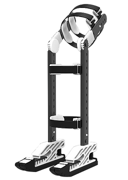
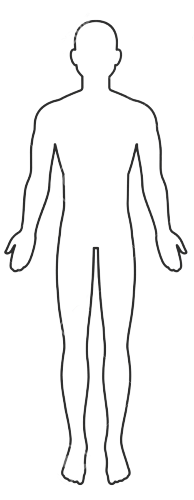
I designed a hands-free crutches called "FLEX" that not only aids in walking but also free the users' hands so that they can be independent in the recovery process. FLEX provides a more natural support as compared to normal crutches as it mimics the movement of leg and feet.
FLEX is designed to cater to the people from the 5th to the 95th percentile.
Healing process
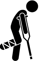


First stage:
Patient uses 2 crutches as the support structure to elevate the injured leg. 100% non weight bearing.
(My product focuses on this stage).
Second stage:
Patient uses 1 crutches as the support structure. The patient can walk with both legs, while placing minimum pressure to the injured leg.
(My product focuses on this stage).
Third stage:
Patient no longer uses crutches as support. However, it is advisable for patient to avoid strenuous activities
Last stage:
Patient makes full recovery.
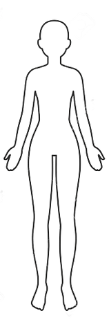
Anthropometric Data Summary
Feet length:
226.3mm - 292.9mm
Overall standing height: 1540mm - 1790mm
Crotch height: 730mm - 865mm
Thigh thickness:
120mm -160mm
Link:
345mm - 410mm
Overall standing height: 1640mm -1905mm
Crotch height: 775mm - 920mm
Thigh thickness:
120mm -190mm
Link:
375mm - 450mm
Natural feet movement /Gait
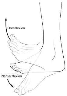
Inspired by the bionic leg, I do want to mimic the movement of the feet in my design. In my current design, now only the knee joints are able to rotate freely. The so-called ankle joint is fix in place so I will be changing it to rotational mechanism instead. However, it won’t be moving 360 degree since it will be mimicking the movement of a human ankle joint. There are many types of movements involved but I will be solely focusing on dorsiflexion and plantar flexion.
Dorsiflexion is the action of raising the foot upwards towards the shin. It means the flexion of the foot in the dorsal, or upward, direction. People use dorsiflexion when they walk. During the middle stages of weight bearing and just before pushing off the ground, the foot will reach its end range of dorsiflexion. For a movement to be considered dorsiflexion, the foot should be raised upward between 10 and 30 degrees.
Plantar flexion is the opposite of dorsiflexion and involves moving the foot in a downward direction, toward the ground. Plantar flexion has a normal range of motion from about 20 to 50 degrees from the resting position.
Prototypes (knee joint)


For the knee joint prototype, I tested out two types of knee joints. One point knee joints and two point knee joint. I chose one point knee joint in the end as it was not necessary to have 2 point knee joint.
Prototypes (support)
Out of all the prototypes, I chose prototype 4 as I did not want the leg support to hover like prototype 1. Prototype 4's design are much better suited for my objectives.


Prototypes (leg support/height adjustment)
Here is the preview of the 5 lower leg support prototypes.
For the leg support, different measurements were taken to figure out the optimal length that i should design my crutches to cater to people ranging from the 5th to 95th percentile.
As the experimentation progressed, I realised that the first few support legs’ did not manage to cater to the people in the 95th percentile. Thus, changing the measurements, the width gradually became shorter while at the same time, the length increases.


Prototypes (strap adjustment holes)
The first method that I tested for the strap adjustment was to have the slots along the lower leg support. However, it proofed to be quite fragile as it easily bends inwards and it is not really appealing to the eyes.
This is how the strapping would be attached to the crutches. However, as it is shown below, as the straps wrap around the plastic, the plastic bend. Having the plastic bend inwards over a long period of time could potentially damage the product. Thus, I had to design the slits differently.


I redesigned it to the sides of the support and it also easier to strap it compared to the first design. This design only requires the users to insert the straps in one direction.


Prototypes (upper thigh strap adjustment)
Using the same method as the lower leg support strap adjustments, I realised that there was an issue. As shown in the thrive picture, when the straps were added, the adjustments holes was blocked. Hence, I needed to make some refinements and cad it out.


Prototype (thigh adjustment)


Flexible thigh adjustments were created to flex to various angles, accommodating to different thigh thickness. However, in prototype A, it was unable to flex much as seen in the photos.


In prototype B, a zig zag bellow was added into the design of the flexible thigh adjustment. I wanted the side to be able to compress but the middle flexed instead. I tried with different size of thickness but with no positive results.


This design is inspired by a wire cable design. Testing the “fish bone” design on mine, it showed great flexibility while still being durable and tough.


Further improving on the design, I added more “fish bone” structures. Designing all the sides to have equal length for injection molding.
Prototypes (clip)


Clip prototype 1 (side release buckle), when designed to have a short length and width made it challenging for the consumers in the 95th percentile to release it.
Clip prototype 2 (center release buckle), inspired by an online design. However, it did not work well with my product. It was not ideal as the consumers would be pushing the buckle against the legs (displayed discomfort) everytime they want to release the buckle.
Clip prototype 3 (slide hook). A workable buckle but does not have much friction to hold the buckle in place.


Clip prototypes (G hook carabiner) started from a simple G hook. Unfortunately I quickly learned that it would loosen due to the constant movement (walking). Thus, adding an inspiration from carabiners helped to strengthen the grip of the buckle to avoid it coming loose.
Possible improvement is to increase the thickness of the clip to create more surface area for the fingers to press against
Feet Size

Prototypes (feet)


The feet is designed to mimic the delicate movement of human feet in terms of the dorsiflexion and plantar flexion.
Feet prototype 1 has two springs to act as the axis of the angle.
With this concept, i need to make sure the front spring is able to stay compress and unable to flex as much in the first stage of recovery but in the second stage of the recovery stage, the front spring can gradually be able to move and flex more.
I do want to consider and explore other designs that are more simple and less complex.


Feet prototype 2 was another design that bends and flex without any mechanism (spring).
As shown above, the feet was able to flex, mimicking the movement of a feet flexing.
It was a good change. However, i realised that the heel area, when pressed against the floor, it was unable to distribute the weight properly resulting in an awkward bend.


Mentioned previously, the heel area had an awkward bend. Hence, instead of the rectangular shape, I changed it to a round shape. This time, feet prototype 3 was able to bend and flex with ease.


The thickness in feet prototype 4 was made consistent throughout in preparation for injection molding
Once I made the thickness consistent, there was visual improvement in the flexing of the heel area.
Even with the changes, it did not disrupt the flexing of the forefeet of the flex feet.


In the previous design, there was the through-holes. The structure is not as strong. Thus, I redesigned it and removed the through-holes while still maintaining the wall thickness.
This is the final prototype design. I am happy with it as it factored in all the considerations I had at the beginning for this product.
Prototypes (feet forestop)


The forestop prototype 1 was designed to be placed in between the teeth at the forefeet to make it stiff for the first stage of recovery. After placing the stopper inside, as shown in the picture below, the size fits securely to ensure that the feet is unable to flex.
My original idea was to be able to use both sides of the stopper. One side (with the teeth in between the teeth of the flex feet) to make the flex feet stiff and then turn over to use the other side after the first stage of recovery to have slight flexing movement with slightly more flexibility as the person recovers. However, I was only able to use one side with the teeth. Moving forward, I would design a stopper with dual purpose.


Forestop prototype 2 is a completely different design from forestop prototype 1. Forestop prototype 2 was inspired by the rope ladder bridge due to its flexibility.
One side of Forestop prototype 2 when laid complete flat is not able to bend. Placing it inside the forefeet securely stopped the flexing motion of the feet.
On the flip side of Forestop prototype 2 when laid complete flat is still able to bend. Placing it inside the forefeet allows the feet to have slight flexibility to flex.
Sole Rendering
No one likes dirty shoes in their house. Likewise, crutches just like shoes, touches the ground majority of the time. Consumers oftentimes have to wipe the the tips before coming in their house. Thus, designing soles that are interchangeable for both indoor and outdoor are ideal. Better yet, the soles can be washed just like shoes.
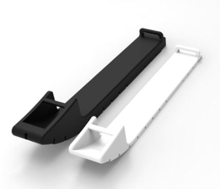

The sole was designed with both outdoor and indoor environment in mind, varying different thickness. The safety of the consumers helped shape what materials used in the sole. Anti slip materials are used to create the sole of the crutches.
To cater to the different environment. The white one has a simple riff across for the indoor environment. The black one, the riff was designed to suit the outdoor environment.
Cad rendering


Final Prototype Assemble


Colour choices


Environment Rendering


Learning Point
This project really challenged me to manage my time well and ensure all the part are precise. It helped me to accept that failure is just a small part of success in the designing process. Throughout the process, there were many hurdles but it also allowed me to grow as an product designer. Coming up with new idea and ways to solve the issues at hand and find the best solution to cater to my target audience.